After multiple rewritings of the code, I think I have a solution to the color sensor that reports the correct colors and luminance. I have also (PURPOSEFULLY!) shorted the LED on the breakout board so as to read the ambient light. This has allowed me to close up the assembly and I am prepared to attach this to the buoy body now.
We have a boat chartered for Monday and so tomorrow I need to construct a camera dolly, get the microcontroller and sensor wires installed in the buoy body, and check the NIR sensor so we are ready for the trip.
Showing posts with label hardware. Show all posts
Showing posts with label hardware. Show all posts
Friday, June 14, 2019

Monday, December 21, 2015
Sunday, December 20, 2015
some headway
during the last few days, i have been working pretty diligently on writing code to in order to make the interactive response to the EEG data more organic. i have been able to get data response (light) mapped to a specific data (waveforms from alpha, beta, etc.). for about the past four days. my observations are that this mapping results in a jumpy output; the lighting is responsive to the latest reading and immediately goes to the next number. more often than not any two adjacent readings have a decent span between the numbers and then lighting rapidly dims or brightens.
my work over these days has been to learn how to engage multitasking on the Arduino stepping out into interrupts and timer functions in order to measure the data over a longer period or grab two data points and then create a smoothing effect over the light changes. or in other words to take value currentReading - pastReading and divide that difference into 8 steps of change (fading in or out).
my work over these days has been to learn how to engage multitasking on the Arduino stepping out into interrupts and timer functions in order to measure the data over a longer period or grab two data points and then create a smoothing effect over the light changes. or in other words to take value currentReading - pastReading and divide that difference into 8 steps of change (fading in or out).
Thursday, December 17, 2015
Wednesday, December 16, 2015
new inspiration HUGO GERNSBACK


Sunday, December 13, 2015
some practice with the new rig
after my initial successes, i then rebuilt the demo with 8 LEDs and cleaned up the wiring to stabilize all the hardware and add additional response range. i practiced for the next couple of hours to develop some control over the system.
i am seriously impressed with the response can already trigger. i realize that this is a simple graphing of one metric in of the EEG profile, but i have already experienced several characteristics of the biofeedback system that are noteworthy.
- it is hard to hold it at a level for a long period of time. i assume this kind of mastery will come with more experience. i can already light the rig with more control after just two hours of practice.
- abstraction is helpful - ironically it is easier to concentrate on the video image of the LEDs and get an active response. i am not sure what is at play here exactly but i theorize that when i look at the actual LED array, i also need to visually process the surrounding world and thus distractions are more plentiful.
- biofeedback - any self imposed distractions (holding my body awkwardly, tensing up, straining, etc.) actually limits my control. it is very meditative. A musician friend made a conjecture that such feedback could help in voice training so people could monitor the tension in their bodies. Very Jedi indeed.
"Do or Do Not... There is no try. - Yoda to Luke on Dagobah."
POC - EEG linked control

i imported the code from the tutorial and had only one small serial method change to make in order to update it to Arduino 1.0. My adapted code here.
my next challenge was to pair the headset and receiver. after re-reading the original directions, i realized it was a simple order of operations problem. to pair one must start with both off (including the headset must not be worn yet). power up the receiver module and then power up the headset. you may then put the headset on the subject. anytime i did not follow those directions strictly the system wouldn't pair.
within minutes i could watch changes in the LED responses; i tracked changes to emotional and tension levels
Friday, December 11, 2015
lots of prep to get ready
i dug in hard today on the project. after cracking the case of the receiving unit of the Neurosky, i spent a bit of time confirming pin outs and making sure my model matched the information i have gathered on the process. i started to wire up the bread board and i realized i was missing the voltage regulator; where the arduino sends data at 5v, the dongle takes a 3.3v signal. there were many reports of people burning out the dongles over a period time with this over voltage. suggested is the SparkFun Logic Level Converter - Bi-Directional
sigh...
so i sucked it up ordered a piece or two from amazon prime and paid for next day shipping and I will have it tomorrow. i realized as i continued to read up on the reasons why the voltage needed reduction that i could simply build a voltage divider as the team from Make a Mind-Controlled Arduino Robot had done. this is a simple process where you pass the voltage across two resistors in series leading to fractional adjusted voltage.

there are tons of calculators on the web, i used this one today and this one in the past to make multi-voltage supplies.
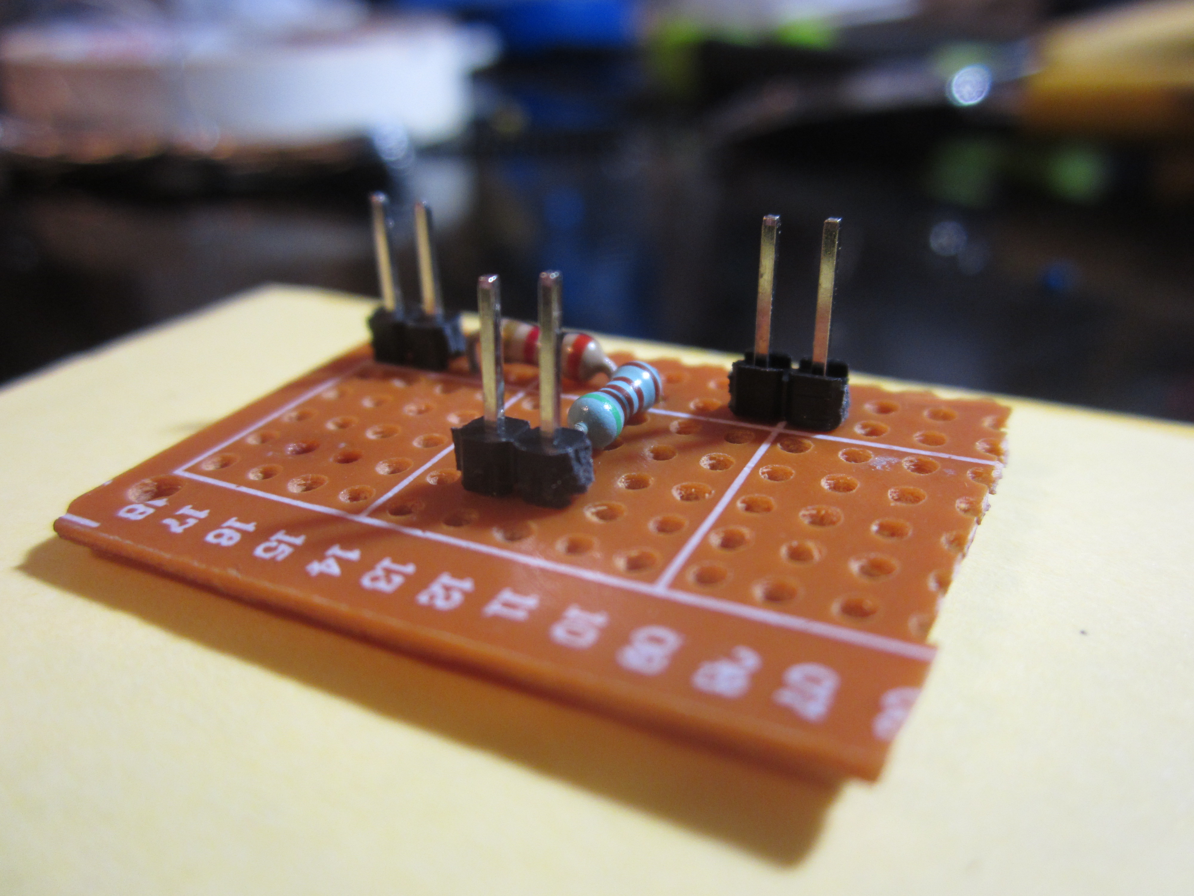
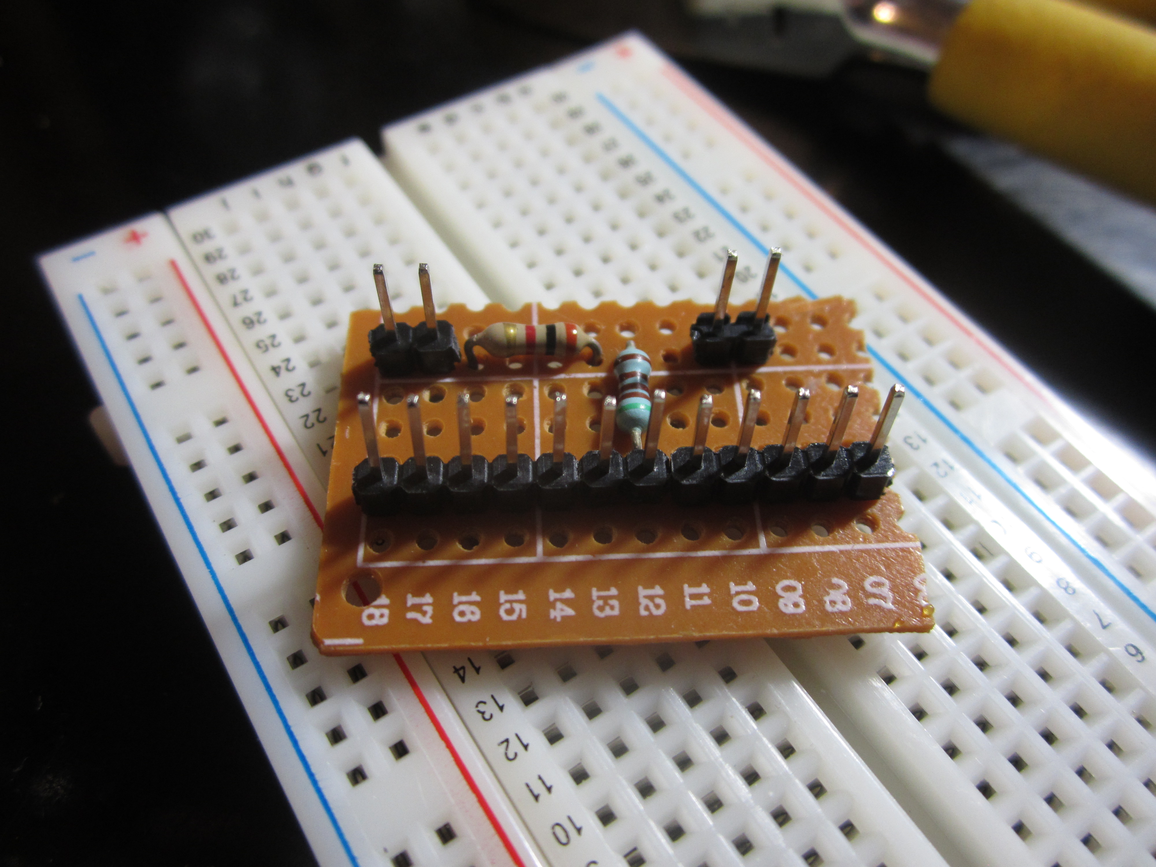
this is what I ended up with. and it worked beautifully with R1 = 1.8kΩ and R2 = 3.3KΩ
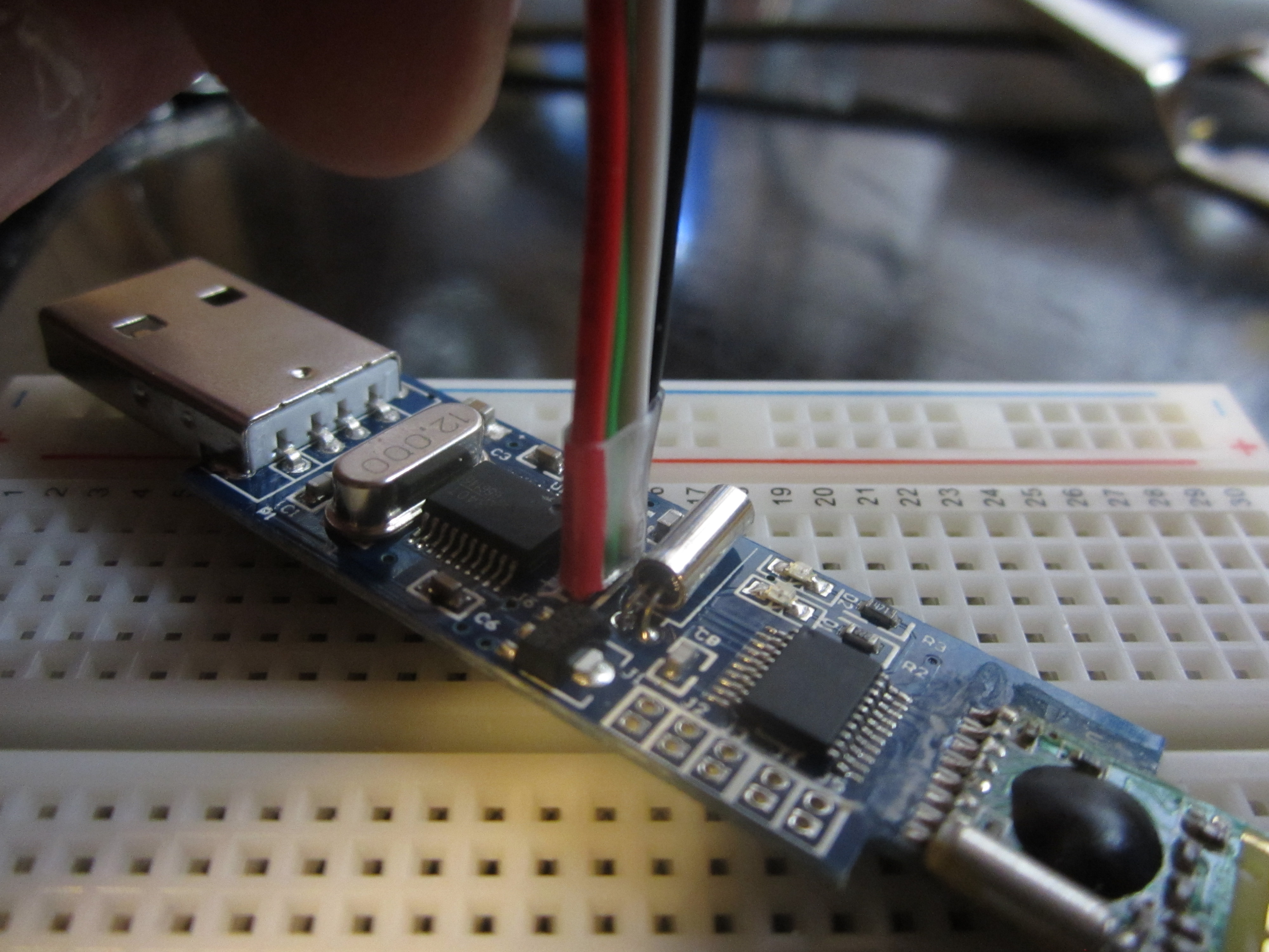
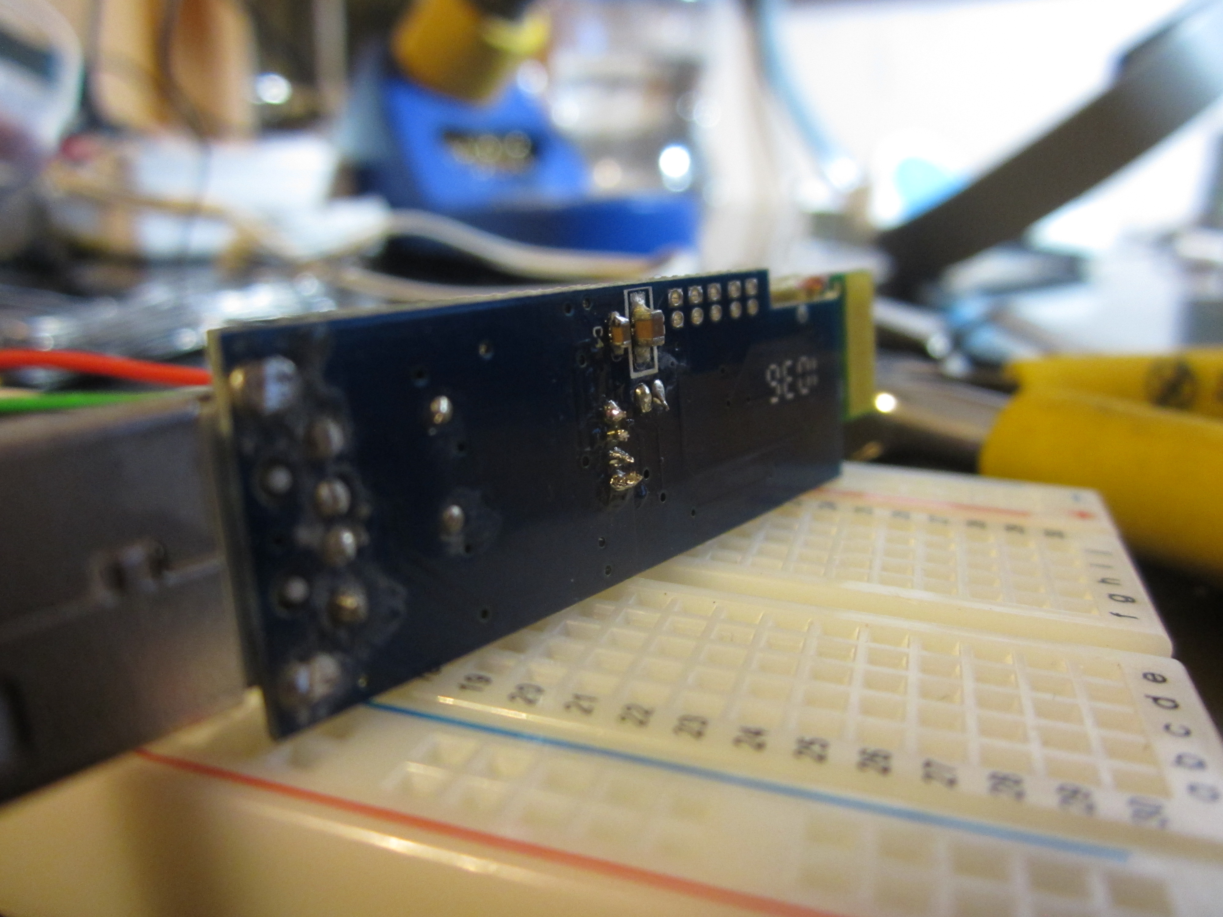 i also soldered wires to the pin-outs on the transmitter/receiver. note the shrink tube on the bundle as a stress relief and careful soldering on bottom to prevent shorts/bridges.
sigh...
so i sucked it up ordered a piece or two from amazon prime and paid for next day shipping and I will have it tomorrow. i realized as i continued to read up on the reasons why the voltage needed reduction that i could simply build a voltage divider as the team from Make a Mind-Controlled Arduino Robot had done. this is a simple process where you pass the voltage across two resistors in series leading to fractional adjusted voltage.

there are tons of calculators on the web, i used this one today and this one in the past to make multi-voltage supplies.
this is what I ended up with. and it worked beautifully with R1 = 1.8kΩ and R2 = 3.3KΩ
Subscribe to:
Posts (Atom)

