
Thursday, May 30, 2013
full Keannu whoaaaa for the Bucaneer
it is 14 minutes after the opening of a kickstarter campaign for a new 3d printed called the Bucaneer, they have already sold $100 000 in pledges...
Wednesday, May 29, 2013


Tuesday, May 28, 2013
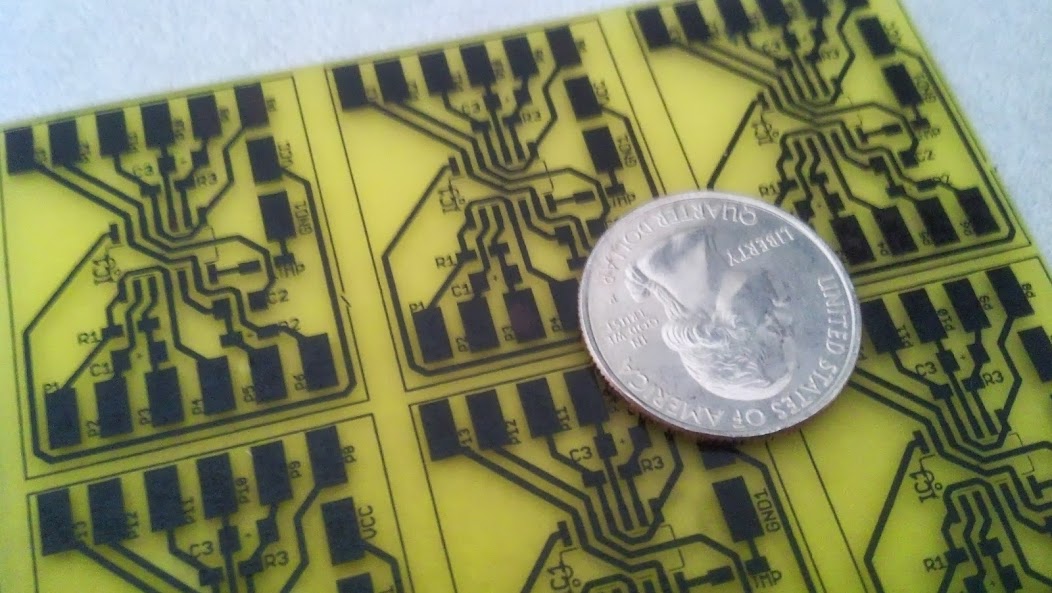
solder masks! oh my!!
solder masks, oh my! i have started investigating the facility and methods need to make solder masks as part of my research to upgrade my homebrew PCB production. i recently purchased some UV curable ink; the price is right at about $15 per 50ml. it takes very very little. your objective should be to spread as thin a film as possible on the pcb. next you set up a typical exposure setup layering a mask over the parts that you don't want to cure (thus a positive process). you can make this tight by clamping the entire layers or use a vacuum exposure frame. i just lay a heavy piece of glass on the top to smoosh it together. when exposed to direct sunlight for about 3-4 minutes, it is enough to cross-link the polymers in the exposed ink.
i didn't understand how to set up the exposure 'sandwich' at first, the first ink never dried and I made a sticky mess of my screens. i soon learned that the cured material will not stick to polypropylene which can be sourced from your friendly 'zipper' food storage bag (Zip sumthin') or those clear sleeves for three hole binders...
so add a drop or two of ink, lay down a sheet of polypropylene, and squeegee the ink to a thin film. lay down and precisely align your mask, and expose. immediately after this first exposure use a rag with solvent (cotton swabs aren't bad either) to dab away the uncured areas over the pads. then set the board out in the light for a while to fully cure the ink.
- i use too much ink; i am too used to painting with a trowel...
- get all the air pockets out from under the poly
- that stuff is hard to get through when fully cured
- clean the pads thoroughly
- easier to scrape away errors before the ink is fully cured
- test all the traces before you got to all this trouble, you are locking yourself out of accessing the traces for repairs
- did I mention the stuff gets hard
 the results/lessons learned from my initial tests were that
all-in-all, i have decided that this is a process i will have to practice many times to get down. the price can't be beat though. i found a dry film called Dynamask 5000, this is a film that i will cut to size and apply with the laminator. it uses a negative process close to the photo-intaglio processes i used to do in school. i will report on this later.
Monday, May 27, 2013
Sunday, May 26, 2013
first SMT experiments
i used solder paste and my normal brutish sized soldering iron... this is magic!


Saturday, May 25, 2013
improved toner transfer methods
 for about a year i have been making my own PCB's by using toner transfer methods. i have been able to make some pretty nice boards with very good results with all kinds of substrates; i have used plain paper, glossy junk mailer/magazine pages, and commercial transfer paper. the results have been very strong using the transfer paper, a dextrin coated sheet that the Laserjet easily prints to.i have been using the household iron method to remelt the toner to the board (simply put print side to copper and apply heat and pressure). i have found you need to be careful, because you can smear the molten toner. to solve this i have adapted a technique from the PulasFX forums where you use a hardwood dowel to roll the board between the iron and dowel. the action takes a little to master but it does quite well, i also bought a rolling pin and will sometimes go to Printmaking and roll right on top of the department hotplate.
the big improvement is a new laminating machine to assist with the toner transfer methods for making resists for my PCB's. i still use the iron to tack the transfer to the board but now the heavy lifting (pressing) is done with the laminator with a few caveats, the machine will grudgingly accept 1.6mm (1/16in) inch boards but i do not recommend it. the .8mm (1/32) boards do very well and last Thursday, i was able to fabricate some SMT plans with .275mm traces. i still have some smearing (i need practice on the number of passes in the laminator), but they look really awesome otherwise.
Friday, May 24, 2013
Otto's Ghost will be haunting Greensboro for Art in Odd Places (AiOP)
it is raining good news, i have received notification that Otto's Ghost has been accepted for the Art in Odd Places 2013: NUMBER in Greensboro, NC. the exhibition is a short period at the beginning of November 2013 in conjunction with the Southeastern College Art Conference (SECAC).
the boilerplate for the show:
AiOP is an artist-led initiative to present art that stretches the possibilities of the public realm. It began at the 1996 Olympics in Atlanta, and migrated with Ed Woodham to New York, taking place years later in the Lower East Side and East Village. Since 2008, the festival has taken place on 14th Street in New York City. We are excited to bring the festival to Greensboro for the first time and look forward to seeing it take place along Elm Street, one of the city’s most vibrant thoroughfares.i have proposed to instll the project in a beautiful huge Magnolia tree located approximately at 500-598 E McGee St on the triangular green belt wedged between McGee, Elm and RR tracks. The geo coordinates are 36.06807, 79.79043 (paste into google maps). link to the map
Thursday, May 23, 2013

Wednesday, May 22, 2013
Otto's Ghost
some time ago i began to play with a solar sound circuit as research in autonomy, electronics, sound installation, etc. i had very vague feelings about how to build upon this project. this spring, i decided that my summer project would be to go for a truly embedded sound installation in the forest that surrounds our University of West Florida. it was very apparent that the many days of sun per year and dramatic shifts in the weather will create some manner of hybrid ecology of machine and nature as a resulting soundscape. in April, i applied for the Faculty Scholarly and Creative Activities Grant to seed the project. i applied for funding to pay for some new tools and to pay some summer assistants to help me realize the project. i am happy to report that it was funded.
 so i commence this summer in flurry of buying new equipment and starting a tremendous research period to learn more about PCB fabrication, Surface Mount Technologies, and mass production. i am building a reflow oven, refining my circuit design skillz, trying new techniques in applying resists, experimenting with new etchants, learning to apply solder masks, trying out conformal coatings, etc., etc.
here are gory details, pulled from my application:
my project with the working title, Otto’s Ghost, is a sound installation constructed from dozens of small solar powered circuits placed into the environment of a wooded site. the site and devices form a hybrid ecology between nature (landscape, trees, etc.) and technology (‘chorus’ of miniature sound robots expressing a variety of chirps, buzzes, etc.) Each module of the group can have an individual sound profile from the variety of the on board photovoltaics and values of components used in each piece. the soundscape manifests as the overall composition of the different ‘sonic speciations’ in the group and environmental factors. the generative soundscape of Otto’s Ghost is additionally influenced by environmental factors (diurnal cycle, weather, etc.) situating the environment as a coauthor in the score created by the installation.
Otto’s Ghost grew out of research from 2008, when i began to investigate autonomous machines and sound art in the installations of Ralf Schreiber (1996) who used the Schmitt Hex Inverter integrated circuit. the core circuit, the Schmitt trigger, is characterized by positive feedback where a portion of the output is fed back to input creating a loop gain (amplification) of the signal. this behavior was discovered by Otto Schmitt and documented in his 1937 dissertation on electrical propagation in nerve fibers of squid. Schmitt, now considered ‘a father’ of contemporary bioengineering, is also known for coining the term biomimetics.
Ralf Schreiber is a primary source in the application of these circuits as an aesthetic form. Like Schreiber, i am also using the oscillatory functions of the Schmitt triggers to create sound installations and feedback loops create chirps and buzzes. the current objective requires materials research to climate harden the devices to be implanted into the biological world. the project expands former research, first, in the transformation of the design and, secondly, by reinserting the machine embodiment of Schmitt’s inquiry as an element of the environment and a complication of the ideas of an ecology and (natural) systems to explore the aesthetics of an autonomous collection of machines as (machineorganisms).
Tuesday, May 21, 2013
follow up on the etching
today's test:

note the vivid blue today because more copper chloride is in solution
Monday, May 20, 2013
a new etchant option

 for the past year or so i have been etching my own PCB's. i have experimented and successfully mastered many Toner Transfer resist techniques where a reversal image is applied with heat and pressure. i have had the kind support from our printmakers who allow me to use their Edinburgh Etch tank to burn the boards. and they have been really spectacular, it gives me much pride to deliver a project module to the students with home-brewed PCB's to work upon. it brings it closer to home on multiple levels.
on friday, i was leading a seminar for my summer work group who are assisting my summer project (stay tuned). in the seminar i demonstrated the entire process: drawing a schematic, PCB layout,resist transfer, etching, and then soldering the project. our printmaking facility is shut down for the summer so i did an etch in a photo tray in the UWF FabLab. this was fine as i only needed about 5 boards and it was fresh FeCl so it went relatively quickly. it has spurred me to take the next leap for our lab and start an official 'chemistry' policy in the lab to make sure the students can follow my lead and make their own custom PCB's.
i began more etchant research as i prepare for the discussion i need to have with our Environmental Health and Safety officers. i am concerned with the protocols we will need to establish for material handling and storage. even though we will need to comply to material handling for the 'used etchant' supplies, it would be wonderful to find other processes that use less hazardous raw materials and etchants that will last long term to reduce the waste stream.
for sometime i have been aware of a Hydrochloric Acid (HCl) and Hydrogen Peroxide (H2O2) etchant that seems to have a long life according to the citizen scienctitst and nerdom around instructables.com. the anecdotal evidence suggests that it has a long life that actually increases etching ability as it is used and that it can be extended by adding more oxidizing reagent (H2O2) or simply bubbling air through the mixture to facilitate the oxidation. the reports are that enthusiasts are getting very long usage times reducing the amounts of materials they dispose of. this is fantastic because cupric solutions are highly toxic to the environment and biology. it has even been suggested that electroplating techniques could be used to reclaim a less soluble (less hazardous) and recyclable copper powder. other advantages of this style of etchant is that it doesn't have the horrid staining that is characteristic of FeCl. it will still wreak havoc on your stainless steel sink so you need to exercise caution.
in the past 48 hours, became aware of a small but growing number of individuals using household vinegar (or if you will acetic acid CH3COOH) and H2O2 plus a little salt (NaCl) as an etchant. this well documented in the BLONDIHACKS blog post from Feb. 2012, where the awesome Quinn Dunki details the process of design to fabrication in awesome detail. and here and Steve Hobley has run similiar experiments as detailed in blog posts from 2011. kind of cool is that he has a chemist in his family who comments on the chemical processes at work here and makes it a totally interesting read.
the remarkable point is that common vinegar runs about 5% acid by volume where a considerably stronger corrosive is usually employed.
 i had to do this! tonight i returned to campus with 3% peroxide, household vinegar, and some salt. i can report that it works very well. slower than the fresh FeCl etchants, but very similar to time need when using the Edinburgh bath we have in the printmaking department. in about 30 minutes, i had etched a one ounce copper plate. as Quinn puts it "not having to deal with storage, use, and disposal of a strong acid is worth it."
i have a close associate in photography and thus access to some pretty aggressive Acetic (it is used as a stop) that we can mix down to a reasonable but higher percentage by volume. i can also get vinegar in up to 30% by volume. this is used as weed killer, but it also looks like it is a lightly regulated as a chemistry. i am also thinking of running some tests citric acid which i could pickup at the local brewing supply house. all of which could make the requirements for Health and Safety easier!
i will be running another board tomorrow morning in the resultant etchant, it should go quicker if the reports are correct. and post images... stay tuned!
Subscribe to:
Posts (Atom)
